wikiHow is a “wiki,” similar to Wikipedia, which means that many of our articles are co-written by multiple authors. To create this article, volunteer authors worked to edit and improve it over time.
This article has been viewed 88,599 times.
Learn more...
Testing your bullet cameras off the bike when you are customizing wiring harnesses is a pain when you need power for them. This is especially true if you start chopping the OEM connectors off and building your own.
A "real" lab power supply can run you $100 or more. By converting the cheap (free) ATX power supplies that can be found in any discarded computer, you can get a phenomenal lab power supply with huge current outputs, short circuit protection, and very tight voltage regulation. You'll get +12V, -12V, +5V, -5V, and +3.3V.
Steps
-
1Unplug the power cord from the back of the computer.
-
2"Harvest" a power supply from a computer by opening up the case of the computer, locating the gray box that is the power supply unit, tracing the wires from the power supply to the boards and devices and disconnecting all the cables by unplugging them.Advertisement
-
3Remove the screws (typically 4) that attach the power supply to the computer case and remove the power supply.
-
4Cut off the connectors except for the large Male ATX connector that goes to the Motherboard.
-
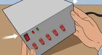
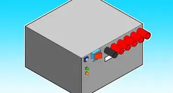
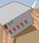
5Drill the holes in your "box" and mount the binding posts, switch, and LED.
-
6Cut your ATX extension cable in half and harvest the female side.
-
7Mount the female side to your box (you will use the dremel to make the hole for this; you may want to use some epoxy to help hold it in).
-
8Bundle the like colored wires together, stripping them and twisting together so that each colored bundle has one connection point.
- You'll end up with a bundle for +12, -12, +5, -5, +3.3, ground, Power OK, Power ON.
-
9Connect the POWER ON (usually GREEN) wire to one side; Connect the other side to the negative side of the LED and GROUND (so, the "out" side of the switch is connected to two wires ... the one coming "out" of the LED and the GROUND bundle).
-
10Connect the positive side to +12V and the other side to the GROUND bundle (which is also connected to the "out" side of the switch as described above).
-
11Connect the bundled wires to +12, -12, +5, -5, 3.3V and ground, respectively.
-
12Connect the POWER OK (usually GRAY, but sometimes BROWN) directly to the POWER SENSING (usually PURPLE or BROWN) wire.
-
13
-
14Check for loose connections by gently tugging on them. Inspect for bare wire, and cover it to prevent a short circuit.
- You may want to put a drop of super-glue to stick the LED to its hole. Put the cover back on.
-
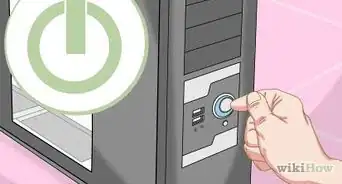
15Plug the power cord into the back and into an AC socket.
-
16
-
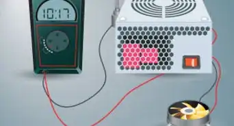
17Plug in a 12V bulb into the different sockets to see if the PSU works, also check with a digital voltmeter.
-
18Finished.


Warnings
- The colors of the wires can vary by manufacturer, so you may have to measure the outputs with a multimeter to find the right ones.⧼thumbs_response⧽
Things You'll Need
- Multimeter
- Drill
- Wire strippers
- Dremel
- Heat shrink
- Heat gun or lighter (to melt the heat shrink)
- Adjustable wrench (for attaching the nuts to the threaded binding posts)
- A switch (all current power supplies use a switch for power)
- LED from an auto parts store (12 V)
- Six (6) binding posts
- Some kind of enclosure box (such as a junk CD-ROM drive case, discarding the "guts")
- A 20-pin female ATX power supply connector to mate with your power supply's connector (such as a 20-pin ATX extension cable off eBay or from your local computer store, after cutting off the male end)